Posts

Astah Unexplored & New Features

Image
I'm currently trying out the reverse-engineering in Astah and am pleasantly surprised by the available features. My sample files are taken from " Full Stack Development with Spring Boot 3 and React " I tried importing the downloaded files from GitHub. Remember to check the "include sublayers" to add files from various subdirectories. Code to Diagram feature Feeling lazy, I used the "Auto Create Class Diagram" function to generate "Simple" class diagrams. Accessing the "Auto Create Class Diagram" feature With a bit of a clean-up and elimination of classes that are irrelevant, the auto-generated class diagrams look great! Auto-generated Class Diagram Auto-Generated Class Diagram The latest feature allows a Definition Note to be automatically created as an UML note. Definitely a most welcomed feature! Right-Click on a model element (Class) to see the available options for "Show Definition Note". The available Definition Notes...

Useful Hacks in Using Astah

Image
MindMap Hack I've been using Astah (download here ) more recently for the MindMap feature and felt to share this wonderful "hack" with you. I jotted some points in NotePad and wish to quickly transfer them into Astah as a MindMap. The easiest way to retain the hierarchy is to use [TAB].  Therefore I could easily transform this Hierarchical List of Points Into Same List of Points in MindMap Here is how it's done: Select all text in NotePad (or equivalent) and Copy (Ctrl-C) Go to Astah and create a New MindMap Diagram Click on Mindmap0 or whatever existing topic and Paste (Ctrl-V) Like magic, the MindMap is created and the hierarchy is retained. UML Deployment Diagram You wish to draw professional-looking diagrams using AWS/ Azure icons. Is that possible & easy to do in Astah? AWS Deployment Believe it or not, the above is drawn in Astah!  Here is how it's done: Go to Tools -> Project Settings -> Set Icon for Stereotype (See Custom Icons for Stereotypes Di...

Using Astah to Understand & Appreciate Published Standards

Image
I'm usually a visual person, hence reading and understanding standards (implementation protocols, etc.) can be quite challenging. In trying to understand and appreciate OIDC (Open ID Connect) from the OIDC website , I used Astah to model my understanding and summarised by understanding in a couple of diagrams. What was more challenging is that there are several flows in OIDC and each can be slightly different. My goal is to not only understand the protocol, but to appreciate how it is applied in my implementation. Fortunately, Astah makes it relatively easy for me to create high-level models that might not have any implementation elements. Remember I'm not implementing OIDC protocol and am modeling the flows in order to better understand them. As such, I'm not exactly interested in creating UML Classes, writing Operations, Attributes, Associations, etc., other than what is instrumental in creating the desired diagrams. Some of the Sequence Diagrams are here: Authorizatio...

Astah - How wonderful you are!

Image
I started using JUDE in the early days of UML modelling and have continued using Astah until now. In the day and age of Agile development, emphasizing "communication over documentation", is UML (and related UML tools) still relevant? I'll give a resounding YES! to the question. While we should do away with extensive documentation , we should still be able to communicate our intent in forms of architecture, design, workflow, processes, etc. In the course of my work in an end-user environment, I use Astah extensively to communicate with development teams, users, vendors and even senior management.  I find it's often a lot easier to use a tool like Astah to draw UML (or pseudo-UML) diagrams than pen-and-paper (or even napkins!). For instance, I can easily move things around, redraw and append/ update the diagram using the tool but not with paper. Some examples of diagrams I'd used in the course of work are below. I used Astah for the following: Share my thought proc...

Template for IT Ops runbook

https://github.com/SkeltonThatcher/run-book-template/blob/master/run-book-template.md https://www.atlassian.com/software/confluence/templates/devops-runbook https://medium.com/@shawnstafford/ops-runbook-16017fa78733

Astah Productivity: How to quickly create UML Classes from Objects in UML Sequence Diagram

Image
I usually begin modelling from a UML Sequence Diagram in order to have a sensing of a list of classes/ objects. However, the downside with starting with the Sequence Diagram is that the classes are not created automatically. Other than having to manually create classes to link to the object (lifeline) which is rather tedious, I finally found a great (undocumented?) feature in Astah that allows me to create a class (automatically) from an object (lifeline) in the Sequence Diagram! BEFORE : the usual steps to creating classes from Sequence Diagrams. Create lifelines and messages as required For lifeline objects that need to be created as a Class, click on the object. The properties panel should show the base class as <<Unspecified>> As the class has not been previously created, we need to create a new Class (usually) with the same name as the object. Click on New and rename the Class Press close on the dialog box. The lifeline object is now an in...

Excel & SharePoint

Objective I needed to prepare an Excel file for importing into SharePoint. Excel First, I need an Excel formula to populate a short name (255 characters) from a much longer name ( found in "col"). The length of the short name is constrained by SharePoint's "single line of text" field. The challenge is to find acronyms within col or if am acronym can't be found, to truncate col to 255 characters. Example:  GNU is Not Unix (GNU) => GNU This is another name => This is another name This is the formula to use.  = IF(ISNUMBER(FIND("(";[col]));MID([col];FIND("(";[col]) + 1; FIND(")";[col]) - FIND("(";[col])-1);LEFT(CLEAN(TRIM([col]));255)) Importing into SharePoint The only error free way to do this is to use Excel to export into SharePoint. Create an Excel table and select it Go to "table tools" tab and choose the "export table to SharePoint list" option within "export...

Unified Data Modelling for RDBMS and NoSQL

Image
The logical model metadata The physical model metadata Note that Blue denotes the RDBMS metadata while Green denotes the NoSQL metadata.

SharePoint Document Library Folders & Tagging

Although I'm aware of the downside of using folders in Document Libraries, I still think it's one of the best ways to categorise files. This is especially true when migrating from file-shares to SharePoint. Furthermore, it's a great hassle to individually tag metadata or column information for each file that I wish to dump into SharePoint. To workaround this issue, the solution is to use automatic tagging in conjunction with the use of folders. See here However, if you structure your Document Libraries with many folders and different levels, you will quickly end up with a different problem: Having to set-up the rules (mapping) for each folder using SharePoint. The easiest way to get around this is to edit the rules directly. This file can be found in the hidden Forms folder as client_LocationBasedDefaults.html. By opening the Document Library using Windows Explorer, you will be able to edit the file. Do so with great care!

Software Architecture Modelling Using C4

Image
UML appears to be dying in the light of the Agile development movement. working software over comprehensive documentation Many have wrongly interpreted this to mean no documentation. I recently read up C4 model for software architecture that describes the software architecture of a system from different depth & perspectives and for a different audience. The author promotes the use of a common vocabulary to describe software architecture using simple-to-understand diagrams. I attempt to do similar in this post using the same case study as that of the C4 article. The differences are: I do not wish to go into  Class (the 4th C) as that requires too much implementation details I replace the 4th C with Concept as I personally find the Conceptual model more relevant and important in appreciating the business domain.   Using Astah , I figured out how I can model the 4C software architecture efficiently using UML. Mind-Mapping I started with a Mind...

Setting Default Column Values for Document

I had the requirement to map the default column values of documents to the nested folder structure it is created/ uploaded into. As an example, a document uploaded into \Document Library\2018\Jan\DeptABC would have default column values accordingly: Year: 2018 Month: Jan Dept: DeptABC The column values (metadata) make searches effective and rather than to have users provide the metadata as a distinct step, we determine the metadata based on the logical (directory) location of the document. To manually configure this, go to [Library Settings] -> [Column default value settings] See here . However, if there are too many columns to configure, a quicker way to do so is to edit the mapping file directly. This file is found in the root of the library: " Forms\client_LocationBasedDefaults.html ". It is an XHTML file that isn't too difficult to comprehend. Do be careful and backup the file before editing.

How to depict (Professional-Looking) Logical Network Diagrams in Astah

Image
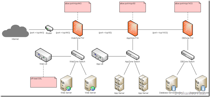
I have always had to create (professional-looking) UML diagrams using Visio-like icons. You’ve got to admit that showing a bunch of boring UML boxes hardly interests anyone less technical (like anyone whose designation has the words “manager” or “director”). This is actually possible in Astah! I’ve created a template for future projects that allows me to produce logical network diagrams that look like the following: To create this diagram, you need to do the following: Assign various icons to stereotypes. I created the following for my use: Create a new UML Deployment Diagram Every element in the diagram is created as a Node The nodes are subsequently assigned the appropriate <<stereotype>>. E.g. Internet is <<internet>>, WebZone FW is <<firewall>>, Web LB is <<loadBalancer>> Ensure the “Icon Notation” is set to “Customized Icon” for each node Instead of the boring boxes, the corresponding icons automatically gets displayed!

AWS Schema

Image
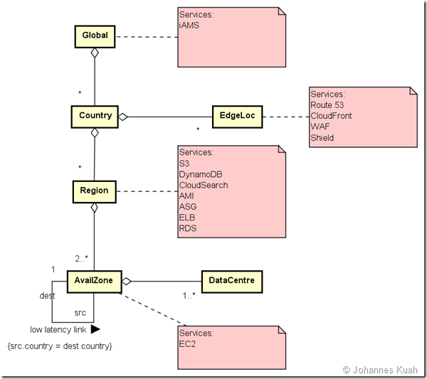
From revising AWS Solution Architect..

SharePoint Schema

Image
From my research, I’ve made some notes as to the structure of SharePoint 2013.

SharePoint OOTB Workflow

Recently, I had the chance to play with SharePoint lists and Document Libraries. I also had the challenge of using SharePoint without the use of Designer. In creating a List or Document Library and associating it with a Workflow, my challenge was to create a View such that I could filter it based on the Workflow status. Thanks to the wisdom of the internet crowd, I chanced upon this article here The status of each workflow is stored as a numeric value but displayed as a string description as follows: NotStarted = 0 FailedOnStart = 1 InProgress = 2 ErrorOccurred = 3 StoppedByUser = 4 Completed = 5 FailedOnStartRetrying = 6 ErrorOccurredRetrying = 7  ViewQueryOverflow = 8 Canceled = 15 (to be confirmed)  Approved = 16 Rejected = 17 (to be confirmed) To filter, compare the value against a numeric constant. For example: show only those that are in progress: = 2 show only those that are not completed: < 5 show only those approved: = 16

Agile Requirements

Capture user stories in the form of: As a <user role/type> I want <some action/ feature/ goal>, so that < benefits from/ reasons for it> Capture acceptance tests in the form of: GIVEN (some context/precondition) [ AND (some more context/precondition) ...] WHEN (event/action performed by user) THEN (expected outcome - what should happen to satisfy user requirement from the user story statement above). See https://www.infoq.com/articles/standardize-requirements-scrum

Web Application Security Issues & Solution using UML

Image
I was once involved in reviewing our company’s application architecture to identify security risks and recommend possible mitigation solutions. Since every organisation has its own unique constraints, available resources, and risk appetite, the solution herein might not apply to other organisations. Nevertheless, this post showcases what one can do with UML to document and explain (pictorially) security flaws in application architecture. The as-is architecture follows. A detailed explanation follows: The system (under design) is a Java Enterprise Application that is deployed in AppSvr (Application Server) within the Internal zone. The deployed application consists of both HTML-based as well as SOAP-based services. The 2 WebSvr’s ([Apache] Web Server) in the DMZ act as proxies. There is a load-balancing appliance used to balance requests to the web servers. A request pool has been created on the appliance (WebPool). The (public) user would access the URL endpoint of the appli...