Software Architecture Modelling Using C4
UML appears to be dying in the light of the Agile development movement.
I recently read up C4 model for software architecture that describes the software architecture of a system from different depth & perspectives and for a different audience. The author promotes the use of a common vocabulary to describe software architecture using simple-to-understand diagrams.
I attempt to do similar in this post using the same case study as that of the C4 article.
The differences are:
I started with a Mind-map to have a good idea of the Context and the main Concepts.
In using Astah, I first create the above Mind-map to capture the system Context and main Concepts.
Next, I performed the following steps:
Next task is to create the Context Diagram.
This proved to be rather easy as the Actors were already created in the earlier step.
I created a UML Use Case Diagram and added a UML Subsystem to depict the SuD.
Call me old-school if you like! I still appreciate the usual UML Use Case Diagram with Actors and associated Use Cases to depict what each Actor does with the SuD in a little bit more detail. This is optional and would be considered a (more detailed) next level of the Context Diagram (Level 1).
At this point, I deviate from C4 in creating a diagram that captures high-level domain concepts. I find the information/ conceptual model useful in describing the SuD in terms of the data/ information it captures. This diagram is commonly known as the Domain Model and is depicted using a UML Class Diagram. In keeping with the 4 Cs, I will call this the Conceptual Diagram.
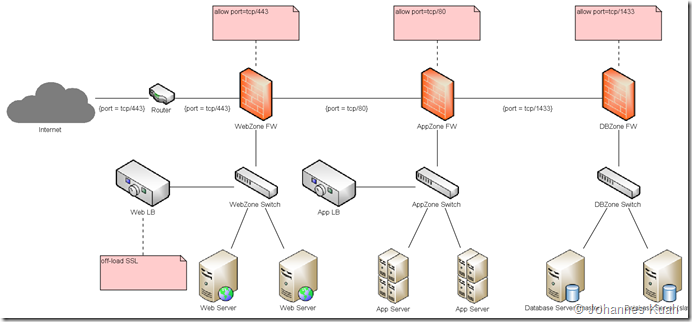
The next perspective in C4 is the Container Diagram which is modeled using the UML Deployment Diagram where every Container is depicted by a UML Node. Constraints are placed on each relationship as necessary.
This is followed by the Component Diagram. Note that the C4 Component Diagram still uses the UML Deployment Diagram (rather than the UML Component Diagram) in order to depict both UML Nodes as well as UML Components.
working software over comprehensive documentationMany have wrongly interpreted this to mean no documentation.
I recently read up C4 model for software architecture that describes the software architecture of a system from different depth & perspectives and for a different audience. The author promotes the use of a common vocabulary to describe software architecture using simple-to-understand diagrams.
I attempt to do similar in this post using the same case study as that of the C4 article.
The differences are:
- I do not wish to go into Class (the 4th C) as that requires too much implementation details
- I replace the 4th C with Concept as I personally find the Conceptual model more relevant and important in appreciating the business domain.
Mind-Mapping
I started with a Mind-map to have a good idea of the Context and the main Concepts.
 |
| Mind-map |
In using Astah, I first create the above Mind-map to capture the system Context and main Concepts.
Next, I performed the following steps:
- For every Human Actor and External System, convert into a UML Actor by selecting them and right-clicking (Convert to UML Model –> Actor)
- For every use case/ feature (sub-topic of Actors), convert into a UML Use Case (Convert to UML Model –> Use Case)
- For every concept, convert to a UML Class (Convert to UML Model –> Class)
Context Diagram
Next task is to create the Context Diagram.
This proved to be rather easy as the Actors were already created in the earlier step.
I created a UML Use Case Diagram and added a UML Subsystem to depict the SuD.
 |
| Context Diagram |
(Optional) Context Diagram (Level 1)
Call me old-school if you like! I still appreciate the usual UML Use Case Diagram with Actors and associated Use Cases to depict what each Actor does with the SuD in a little bit more detail. This is optional and would be considered a (more detailed) next level of the Context Diagram (Level 1).
 |
| Use Case Diagram (Context Diagram Level 1) |
Conceptual Diagram (Personal Preference)
At this point, I deviate from C4 in creating a diagram that captures high-level domain concepts. I find the information/ conceptual model useful in describing the SuD in terms of the data/ information it captures. This diagram is commonly known as the Domain Model and is depicted using a UML Class Diagram. In keeping with the 4 Cs, I will call this the Conceptual Diagram.
 |
| Conceptual Diagram |
Container Diagram
The next perspective in C4 is the Container Diagram which is modeled using the UML Deployment Diagram where every Container is depicted by a UML Node. Constraints are placed on each relationship as necessary.
 |
| Container Diagram |
Component Diagram
This is followed by the Component Diagram. Note that the C4 Component Diagram still uses the UML Deployment Diagram (rather than the UML Component Diagram) in order to depict both UML Nodes as well as UML Components.
") |
| Component Diagram |
I hope this post helps to reconcile C4 and UML. At the same time, C4 is likely the way to go forward in documenting software architecture in a lean and minimalistic manner.
The challenge, however, is that the UML diagrams are certainly not as verbose as those used in C4. At this point, the only viable solution is to depict the description in UML Notes attached to each element.


Comments